Everything you see - Made by Me
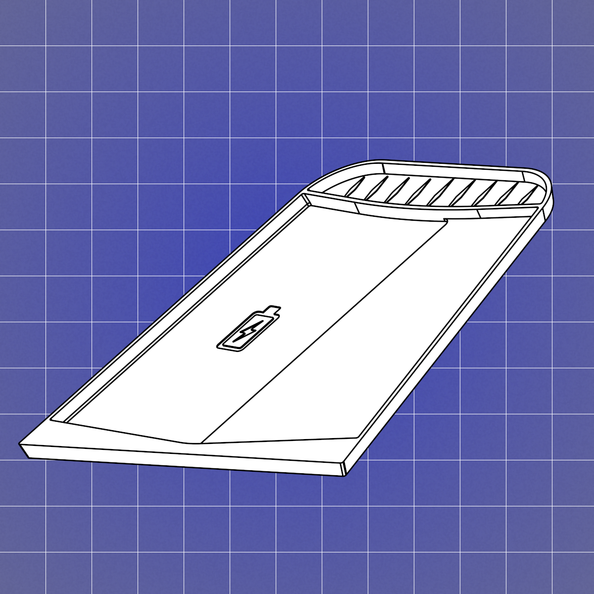
After recently purchasing a new Mustang Mach-E I noticed the wireless charging pad in the car came with a rubber mat which interfered with plus-sized phones in cases. I immediately set out to reverse-engineer the stock part so I could redesign and print a superior replacement which would not impact the charging efficiency.
The key issue with the stock part included with my vehicle was that it included several features which made it impossible for my phone to rest perfectly parallel to the charging coil. In general, the angular misalignment between the two charging coils (between the phone and the car charger) is related by the square of the cosine of the angle between the two coils. This means that a slight tilt of only 30 degrees can lose nearly a quarter of the charging efficiency! All this lost efficiency ends up as heat directly applied to the phone, which is not ideal for the health of the smartphone.
First on the list for redesigns was the removal of the middle “wedge” alignment feature on the stock part, which in my case was lifting up the phone on the right side. Second, was the shortening of the “tray” at the very back of the mat, as it was tilting the phone up at the top. And finally, the charging efficiency of wireless chargers is proportional to the distance between them, so replacing both of these alignment features with a simple shaped depression in the pad would provide a very effective way to solve both issues at once. With the technical objectives met, the only remaining challenge was to recreate the aesthetic flourishes on the stock part. While the charging icon and diamond-pattern ridges on the tray were simple matters of measuring by caliper, the textured “3D hexagon” pattern coating the entire tray was another matter entirely. By default, 3D printing slicers offer no ability to paint-on any kind of texture to horizontal surfaces (and only fuzzy skin can be applied to vertical surfaces).

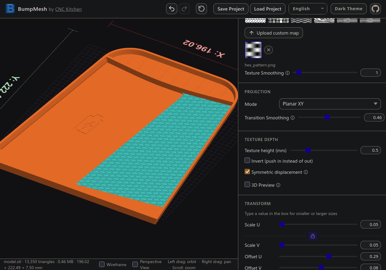
This lead me to use the brilliantly designed web tool from CNC Kitchen called BumpMesh (www.bumpmesh.com). By using this tool and a hand-recreated displacement map (created using GIMP and hand-calculated B/W gradient positioning), I was able to apply the unique pattern to the 3D model for printing. Although visually the texture is very different due to the 3D printing layer lines, the overall feel is remarkably similar to the original. I opted to not use this texture on the phone side in order to get the optimal flat surface needed. The final result was printed in basic 95A TPU with 3 perimeters, 25% rectilinear infill, and variable layer height applied to the Z-level of the diamond pattern to get additional texture from the pattern.
The end result of this design produced a fairly effective replacement part, however there are two potential changes I would consider for future development. First, the overall fit could be adjusted to be even more form-fitting, as the current design is only a reasonable approximation. There are points where an extra milimeter or less of material could provide a much more snug contact. The second would be in using a stiffer elastomer, since using 95A TPU with this print geometry produces a very soft and "floppy" part which could result in the mat sliding and folding over instead of holding its position over the charger. As with any structure the rigidity is determined by the geometry, so increasing print infill or adjusting the overall shape might also work in addressing this possible issue.